PH/ORP-6850

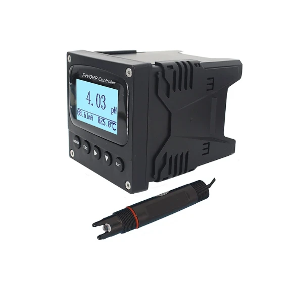
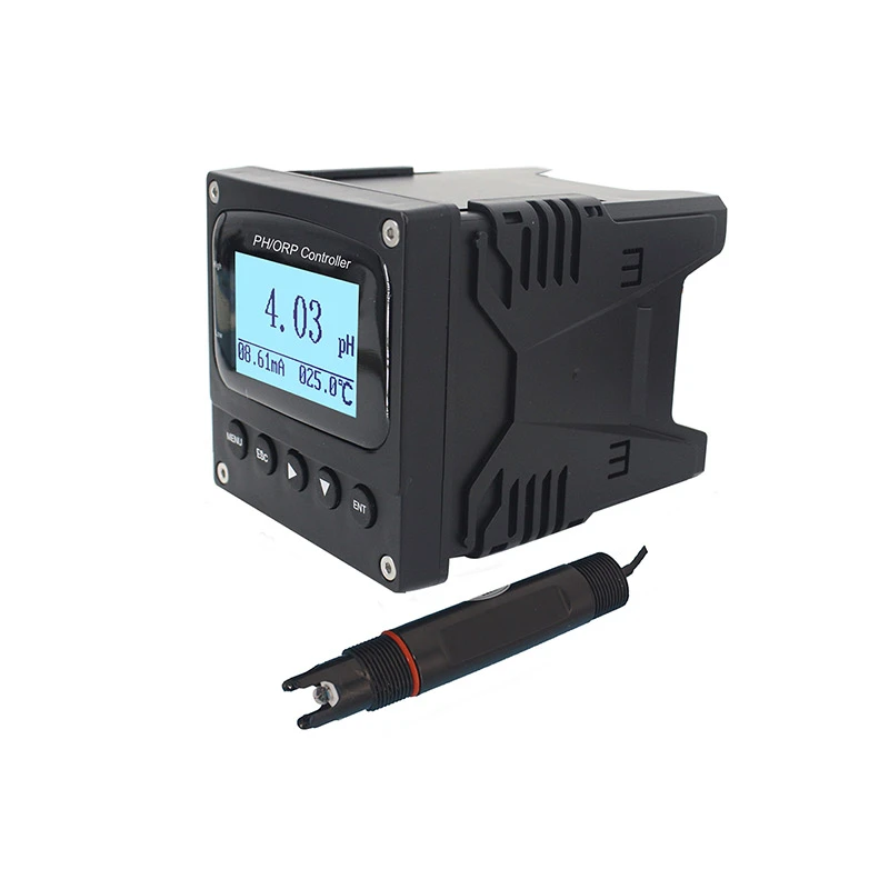
Industrial online PH/ORP controller PH/ORP-6850 is single channel PH or ORP controller. It can measure and control PH and ORP value of water continuously, the PH/ORP controller is applicable for municipal waste water treatment, chemistry, printing and dyeing, paper, medicine, plating and environmental production etc.

Product Details

Product Details

Contact Now

Contact Now

Product Details


I Introduction:

Industrial online PH/ORP controller PH/ORP-6850 is single channel PH or ORP controller. It can measure and control PH and ORP value of water continuously, the PH/ORP controller is applicable for municipal waste water treatment, chemistry, printing and dyeing, paper, medicine, plating and environmental production etc.

In accordance with the environment and characteristics of water industry, as well as the international power supply standard, considering the electricity design in special environment, the PH/ORP controller could be supplied with power 220V AC, 110V AC and safe low voltage 24V AC, 24V DC for selection.

Main Characteristics:

English language display

Measure pH or ORP, high/low limit control, current output, digital communication output (Optional)

It could be set automatic/manual temperature compensation

pH high/low limit alarm light, double relay, alarm delay could be set

Instrument mode isolated transmitting port, max circle resistance up to 750Ω

PID control to actuate and control powered variable value through 4-20 mA output (optional)

Back light of LCD could select power saving mode, timing automatic off, brightness adjust,

High performance CPU, good electromagnetic compatibility

AC input be fused.

ESD over voltage protection is available

Password management avoid non-professional person to operate

Main Technical Index

Measure range

 pH(0~14 pH) ; ORP( -1200~+1200 mV)

Accuracy

+ 0.02 pH; + 1 mV

Resolution

 0.01pH; 1mV(0.1mV optional)

Stability

≤ 0.02 pH/24hr ; ≤ 3 mV/24hr

pH standard solution

4.00/6.86/9.18 (standard),  4.01/7.00/10.01(optional)

Display

128 * 64 dot matrix LCD

Temp. compensation

0–120 ℃, manual / automatic, PT1000RTD

Signal output

 One isolated 4-20mA signal output, max circle resistance 750Ω

Alarm output

high and low limit alarm contact (3A/250 V AC), normal open contact relay

Power supply

AC220V ±10%, 50/60HzR,

AC110V ±10%, 50/60Hz£,  

 DC24V, 0.5A,£,

Power consumption

 ≤3W

Working environment

(1)temperature 0~60 ℃ 
(2)humidity≤95%RH

Outline dimension

96×96×127mm(high×width×depth)

Hole size

93×93mm(height×width)


Outline dimensions and fixed Installation


Insert the controller from the front panel, install the fix clamp

(left and right), tighten with the clamp. 


PH/ORP-6850PH/ORP-6850

 Chart 1  Outline dimensions and fixed installation


Wire Connection


PH/ORP-6850

Chart 2 Rear terminals


Connection Instruction


Note: The jumper can’t remove

1.GND : REF(Black)

2.INPUT+:PH probe signal input port (Transparent)

3.INPUT-:NC

4.GND:TEMP (White)

5.TEMP:TEMP(Green)

6.-V:NC

7. I 1+: 4-20mA output + (PH)

8. I 1- : 4-20mA output - (PH)

9. A +: RS485 +

10. B+ : RS485-

11.H1: High limit relay normal open contact

12.L1: Low limit relay normal open contact

13.COM1: High/Low limit relay common port

14.H2: undefined

15.L2: undefined

16.COM2:undefined

17.N: 220V Power connection

18.GND: Ground wire

19.L: 220V Power connection


Probe Installation

Installation method and Attention-matter

PH/ORP-6850

Chart 3(Several common method of installation)


In order to make sure the probe measure the real value on the pipe, bubbles should be avoided ,otherwise the value will be not accurate, please install according to the following chart: 

PH/ORP-6850

Chart 4(attention matters of pipe installation)


Note:

(1)The probe bypass pipe of the main pipe, valve should be installed in front of it to control the water flow speed, flow should be relatively slow, generally there are steady water flow out of the outlet port is ok. The probe should be installed vertically and should be insert into the active water flow, outlet port should be higher than inlet port which could make sure the probe is in the water solution absolutely.

(2)The probe should be calibrated before installation.

(3)The measure signal is weak electric signal, its cable should be contributed separately, it is not allowed to contribute together in same cable or terminal with other power line, control line etc, which is to avoid interrupt or break the measure unit.

(4)If the measure cable should be lengthen, please contact with the supplier or indicated before place order (generally not longer than 10m)


Correct setting

Soft key function

Soft key

Key function

Function description

PH/ORP-6850

Menu Key

Enter main menu

PH/ORP-6850

Return key

Exit or return to the upper interface

PH/ORP-6850

Right shift key

Select the digit circularly,

Select sub-menu, change the digit value

PH/ORP-6850

Down shift key

Select sub-menu

Change the digit value

PH/ORP-6850

Confirm key

Confirm selected sub-menu

Confirm selected value


Main Interface:

PH/ORP-6850

Note: Under main interface through press “ PH/ORP-6850 ”to shift to browsing interface,no need to enter 'Menu Option' interface, it could browse setting value.

Browsing interface

PH/ORP-6850

Note: Browsing interface through press“ PH/ORP-6850 ”could check

parameter state in turn, through press “    PH/ORP-6850   ”return to main interface.


Main Menu Interface

PH/ORP-6850


Under main interface, press “PH/ORP-6850” key to enter user login interface, after input password “ 0000 ” to press “ PH/ORP-6850 ”to enter “ Menu Option ” interface, this interface menu instruction as follow:


No.

Menu Name

Menu content instruction

1.

Parameter

Set probe type and compensation

2.

 Relay & Alarm

Set pH or ORP High/ Low set point and Relay delay

3.

4-20mA Output

Set pH or ORP transmission capacity start range transferring

4.

PID control

To actuate and control powered variable value through 4-20 mA output (Optional)

5.

Modbus RS485

Set communication baud speed and address

6.

Backlight option

Set back light normal ON, delay off and dimming

7.

Factory reset

Recovery the instrument parameters to factory setting

8.

Calibrate

This menu only open when select pH probe

9.

Password change

Reset login password


Parameter Interface

PH/ORP-6850


Note: press “ PH/ORP-6850 ” or “PH/ORP-6850 ” to select “ Probe type ” or  “ Temperature compensation” parameter setting,press “ PH/ORP-6850  ” to enter.


Relay & Alarm Interface

PH/ORP-6850


Note: press “ PH/ORP-6850 ” or “ PH/ORP-6850 ” select “ High Set Point ” , “ Low Set Point ” or “ Relay delay ” parameter interface,press “ PH/ORP-6850 ” to enter.


4-20mA output Interface


PH/ORP-6850PH/ORP-6850PH/ORP-6850


Note: press“ PH/ORP-6850 ” or “ PH/ORP-6850” input parameter value,press“ PH/ORP-6850”to save.


PID Control Interface

PH/ORP-6850PH/ORP-6850PH/ORP-6850

Note: Press “ PH/ORP-6850 ” or “ PH/ORP-6850 ” to select and enter into“PID ON/OFF”,“Output Port” and “PID Parameter”, press “ PH/ORP-6850 ”to save. 


Modbus RS485 Interface

PH/ORP-6850


Note: Press “ PH/ORP-6850 ” or “ PH/ORP-6850 ” to select, press “PH/ORP-6850  ”to save.


Back light option


PH/ORP-6850PH/ORP-6850PH/ORP-6850


Note: Press “ PH/ORP-6850 ” or “ PH/ORP-6850 ” to select and enter into  “Delay off ”, “ Normal on” or “ Dimming ”, if select “Delay off”, then need to input '“Set Time”, if select “ Dimming ”, then need to input “ Brightness ”, press“ PH/ORP-6850 ”to save.


Factory Reset Interface

PH/ORP-6850


Note: Press “ PH/ORP-6850 ” or “ PH/ORP-6850 ” to select “ Yes ” or “ NO ”, press“ PH/ORP-6850 ” to save.


Factory default parameter

Menu name

Setting range

Factory parameter

   Probe type

PH/ORP probe

PH probe

Temp. comp

Auto/manual

manual

Manual temp.comp value

0 ~ 120 ℃

25 ℃

High alarm close value

      pH: 0.00 ~14.00

     pH: 13.00 pH

ORP:- 1200 ~ + 1200 mV

 ORP:+ 1200 mV

High alarm open value

   pH: 0.00 ~ 14.00

pH: 12.00 pH

ORP:- 1200 ~ + 1200 mV

ORP:+ 1100 mV

Low alarm close value

 pH: 0.00 ~14.00

     pH: 2.00 pH

ORP:- 1200 ~ + 1200 mV

  ORP:- 1200  mV

Low alarm open value

   pH: 0.00 ~14.00

pH:  3.00   pH

ORP:- 1200 ~ + 1200 mV

 ORP:- 1100  mV

Relay delay time

0-99S

0


4mA value

   pH: 0.00 ~ 14.00

pH:  0.00   pH

ORP:- 1200 ~ + 1200 mV

 ORP:- 1200  mV


   20mA value

  pH: 0.00 ~ 14.00

pH:  14.00   pH

ORP:- 1200 ~ + 1200 mV

 ORP:+1200  mV

PID Control

ON/OFF

OFF

   Set Point

0-14ph

7PH

PID Value

P: 0-500

P: 0.5

I: 0-9999

I: 300 S

D: 0-9999

D: 10 S

Control Cycle

1-9999  

0005 S

PID Direction

Forward / Reverse

Forward

User password

0 ~ 9999

0000

Backlight

Normal ON/Delay

Delay

Delay time

0 ~ 99  S

60 S


Calibration Interface


PH/ORP-6850


Note: When put probe into the solution, the controller display current measured solution PH value. This part operation refer to “ PH controller calibration“ part.


Password Change Interface


PH/ORP-6850


Note: Input new password , press“ PH/ORP-6850”to save.


Maintenance


1.PH part
1)Maintenance of instrument
The input terminal of instrument (insert port of probe) should be keep dry and clean, avoid dust and moisture invade.
It is not allowed to put the probe in protein solution and acidic fluoride for long time, avoid touch with silicone oil.
After long time use, if we found the slope is lower, it could be put the probe into 4% HF solution(hydro fluoride acid) 3-5 seconds, and then clean with distilled water, then dip into 0.1mol/L hydrochloric acid, that will renew the probe.
To measure more accurate, the probe should be calibrated periodically and wash with distilled water.
The instrument should be installed at a dry place or in a electric cabinet, to avoid water drop spatter or wet which will cause leakage of electricity or measure errors.

2)Calibration of instrument:
Before calibrate, check if the wire connection of instrument is correct or not, power on and wait 20mins.
Prepare three kind of standard solution:4.00pH, 6.86pH 9.18pH
Clean the probe with distilled water and dry with filter paper, put the probe into standard buffer solution 4.00PH, mix it slowly till the display value is steady.
Through the menu to enter probe calibration interface, the screen display '4.00PH calibration', in the middle it display probe output pH value, till the pH value is steady and press ' ENT ' key to operate calibration, when calibration finished successfully it will indicate success.
Repeat the upper two steps, calibrate the 6.86 and 10.01PH. After finish each step calibrate, probe should be cleaned by distilled water and dry with filter paper, then it can be put into the next solution to calibrate.


2.ORP part

1)Preparation one kind of ORP standard solution 470mV (240mV or others optional), in order to improve the measuring accuracy, the calibration solution mV value need to close to the measuring value.

Clean the probe with distilled water and dry with filter paper, put the probe into standard buffer solution 470mV (240mV or others optional) mix it slowly till the display value is steady.
Through the menu to enter probe calibration interface, the screen display '4.00PH calibration', in the middle it display probe output pH value, till the pH value is steady and press ' ENT ' key to operate calibration, when calibration finished successfully it will indicate success.

2)ORP probe checking:
Not like pH probe need be calibrated by standard solution, the ORP probe need to use standard solution to check, the most important is to check if the probe is workable or not.
Clean the probe with clear water and dry it with soft towel.
Put the ORP probe into the mV standard solution which is prepared. wait till the reading is steady.
Watch the display value is close to mV standard solution or not, if the errors is within range ±35mV, the electrode could be used otherwise it need to be replaced.


4-20mA current output formula


1.PH Current output formula:
Factory setting define output current value is :0 pH is corresponding value of 4 mA; 14 pH is corresponding value of 20 mA.
I = ( D - 4 mA corresponding value)× ( 16 / (20 mA corresponding value- 4 mA corresponding value) ) + 4.00
I = ( D - 0 )× ( 16 / 14 ) + 4.00
Note: I is output current value 4 mA≤I≤20 mA
D is pH value displayed by the instrument 0.00pH≤D≤14.00pH

2. Formula of ORP current output:
Factory setting define the output current is :-2000mV is corresponding
value of 4 mA; +2000mV is corresponding value of 20 mA.
I = ( D - 4 mA corresponding value )× ( 16 / (20 mA corresponding value - 4 mA corresponding value) ) + 4.00
I = ( D – (-2000) )× ( 16 / (+2000 – (-2000)) ) + 4.00
I = ( D + 2000 )× ( 16 / 4000) ) + 4.00
Note:I is output current value 4 mA≤I≤20 mA
D is ORP value displayed by the instrument -2000mV≤D≤+2000mV


Fault Judgments and Trouble Clearing


(1)No display of the controller?
Answer: the power is not well connected or blown fuse. Check the power supply line and fuse.
(2)Value can be displayed but not stable ?
Answer: Probe cable is wet or ceramic of probe is polluted. Check probe cable, clean ceramic core(0.1mHCL).
(3)Solution PH4.00 and PH6.86can not be adjusted ?
Answer: Outside of probe is polluted, probe cable is wet, probe is broken or there is cracks, ceramic core of probe is blocked. Clear probe (0.1mHCL), check the probe cable, replace probe, clean ceramic core (0.1mHCL).

(4)Numbers response slow ?
Answer: thin film of probe or ceramic core is polluted. Clean the whole probe.
(5)The actual pH value change a lot but the instrument display pH value change very small?
Answer: ceramic core of probe is blocked, probe fall off/perish, slow response. Clean probe (0.1mHCL), use recovery solution.
(6)Display value of instrument not change ?
Answer: Probe broken, probe cable short circuit. replace probe, check probe cable.
(7)Relay not active or pH value not change after dosing chemicals ?
Answer: Relay broken; wrong setting of the instrument and chemical solution is not enough. Contact supplier to replace relay, change settings, add chemical solution.


Complete Instrument


PH Controller

1pc

PH probe

1pc

Fixed clamp

1pair

Operation  manual

1pc

Calibration solution

1set


Get in Touch

If you are interested in our products, you can choose to leave your information here, and we will be in touch with you shortly.

* Name

* E-mail

Phone

*Message

FAQS

Frequently Asked Questions (FAQ) About PH/ORP-6850
1                  


Related Products

right
right
RO Membrane

RO Membrane

PH-6800

PH-6800

WS-9200/9250

WS-9200/9250

RO-8100

RO-8100

RO- 8200

RO- 8200

ORP-6800

ORP-6800

PH/ORP-600

PH/ORP-600

JIRS-803C

JIRS-803C

Related News

right
right
Guide to Ensuring Water Purity for drinking water tds Monitoring

Jul.01,2026

Guide to Ensuring Water Purity for drinking water tds Monitoring

Ensuring Water Purity: The Ultimate Guide for Drinking Water TDS Monitoring Maintaining high water quality standards is essential for public health and industrial safety. One of the most critical metrics for assessing water purity is Total Dissolved Solids TDS, which represents the combined content of all inorganic and organic substances dissolved in water. Utilizing high-precision equipment for drinking water tds measurement allows facilities to detect contamination and ensure that filtration systems are operating at peak efficiency. In this guide, we will explore the technical aspects of TDS monitoring and how advanced transmitters provide the reliability needed for modern environmental monitoring.

Understanding the Conversion of Electrical Conductivity to TDS

Jun.29,2026

Understanding the Conversion of Electrical Conductivity to TDS

Understanding the Conversion of Electrical Conductivity to TDS In water quality analysis, measuring the purity of a liquid often involves understanding the relationship between electrical conductivity to tds Total Dissolved Solids. While conductivity measures the ability of water to pass an electrical currentwhich is directly influenced by the concentration of ionized substancesTDS represents the total amount of mobile charged ions, including minerals, salts, or metals dissolved in a given volume of water. For professionals in environmental monitoring and water treatment, mastering this conversion is essential for maintaining system efficiency and ensuring regulatory compliance.

Industrial Guide to Electrical Conductivity Salt Water Monitoring

Jun.27,2026

Industrial Guide to Electrical Conductivity Salt Water Monitoring

Understanding Electrical Conductivity Salt Water Monitoring for Industrial Precision In the realm of water quality analysis, measuring the electrical conductivity salt water levels is a critical process for maintaining industrial efficiency and environmental safety. Conductivity serves as a direct indicator of the concentration of dissolved ions, which is essential for industries ranging from desalination plants to chemical manufacturing. Accurate monitoring prevents equipment corrosion, ensures product purity, and supports regulatory compliance. By utilizing advanced instrumentation, operators can achieve real-time insights into salt concentrations, allowing for immediate adjustments in water treatment processes to avoid costly downtime.

Technical Guide to Industrial ec meter circuit Design and Use

Jun.26,2026

Technical Guide to Industrial ec meter circuit Design and Use

Understanding the EC Meter Circuit: The Heart of Water Quality Analysis Electrical Conductivity EC is a fundamental parameter in environmental monitoring, aquaculture, and industrial water treatment. At the core of every reliable measurement device is a sophisticated ec meter circuit , which converts the physical conductance of a liquid into a precise digital reading. Whether you are managing a boilers deoxygenation process or monitoring nutrient levels in hydroponics, understanding how the circuit handles signal amplification and temperature compensation is key to ensuring data accuracy. This guide explores the technical intricacies of EC circuitry and how it integrates into professional water quality controllers.

Professional Guide to drinking water testing for tds and Purity

Jun.25,2026

Professional Guide to drinking water testing for tds and Purity

Drinking Water Testing for TDS: Ensuring Pure and Safe Water Quality Maintaining high water quality is essential for both health and industrial efficiency. When performing drinking water testing for tds , professionals seek to measure the Total Dissolved Solids TDS, which indicates the concentration of dissolved inorganic salts and organic matter in water. Whether you are managing a municipal water plant or a high-precision industrial facility, understanding the conductivity and TDS levels is the first step toward effective water treatment. In this guide, we explore the technical aspects of TDS measurement and the advanced instrumentation required for accurate monitoring.

Industrial TDS Controller Machine for Water Quality Management

Jun.23,2026

Industrial TDS Controller Machine for Water Quality Management

Maintaining precise water purity is critical for various industrial, agricultural, and domestic applications. A tds controller machine serves as the brain of a water treatment system, continuously monitoring Total Dissolved Solids TDS to ensure that water quality remains within specified limits. Whether you are managing a hydroponic farm, a pharmaceutical lab, or a large-scale reverse osmosis plant, having an automated way to regulate mineral concentrations is essential for efficiency and product consistency. In this guide, we will explore how these machines work and why they are indispensable for modern water management.

Optimize Water Purity with a TDS Controller in RO System

Jun.21,2026

Optimize Water Purity with a TDS Controller in RO System

Maximizing Water Purity: The Role of a TDS Controller in RO System Achieving consistent water quality is the primary goal of any reverse osmosis setup. A tds controller in ro system acts as the brain of the filtration process, monitoring Total Dissolved Solids TDS in real-time to ensure the output meets specific purity standards. Without precise control, users often face the dilemma of either wasting too much water or compromising on the purity of the drinking or process water. By integrating an intelligent controller, you can automate the blending process, extending the life of your membranes while maintaining a perfect balance of minerals.

Optimize Water Quality Using a tds controller for ro Systems

Jun.20,2026

Optimize Water Quality Using a tds controller for ro Systems

Optimizing Water Purity with a TDS Controller for RO Systems Maintaining the ideal balance of minerals in purified water is critical for both industrial processes and residential health. A tds controller for ro acts as the brain of a Reverse Osmosis system, ensuring that Total Dissolved Solids TDS remain within a precise range. Without an effective controller, RO systems can either strip too many essential minerals or allow contaminants to leak through as membranes age. This guide explores how these devices function, their importance in water treatment, and how to choose the right model for your specific needs to ensure consistent water quality.

If you are interested in our products, you can choose to leave your information here, and we will be in touch with you shortly.


en_USEnglish